-
Feature Request
-
Resolution: Won't Do
-
Major
-
None
-
False
-
False
-
Undefined
-
-
2021 Week 28-30 (from Jul 12), 2021 Week 31-33 (from Aug 2), 2021 Week 34-36 (from Aug 23), 2021 Week 37-39 (from Sep 13), 2021 Week 40-42 (from Oct 4), 2021 Week 43-45 (from Oct 25), 2021 Week 46-48 (from Nov 15), 2021 Week 49-51 (from Dec 6th), 2022 Week 02-04 (from Jan 10), 2022 Week 05-07 (from Jan 31), 2022 Week 08-10 (from Feb 21), 2022 Week 11-13 (from Mar 14), 2022 Week 14-16 (from Apr 4), 2022 Week 17-19 (from Apr 25), 2022 Week 20-22 (from May 16), 2022 Week 23-25 (from Jun 6), 2022 Week 26-28 (from Jun 27), 2022 Week 29-31 (from Jul 18)
Motivation
The main goal is to improve the usability and experience when dealing with lines while creating and maintaining BPMN processes. BPMN layouts are typically relying on horizontal / vertical aligned nodes and use of orthogonal segments for lines.
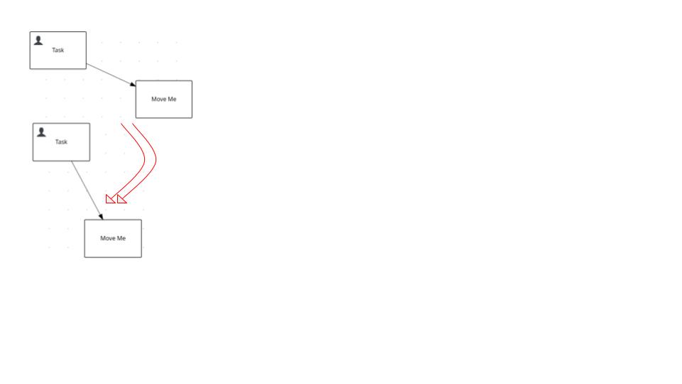
Actually the BPMN editor provides support for polylines, but it doesn't consider orthogonality of segments. As a result, orthogonality cannot be used properly. When moving connected nodes or bendpoints around, it is hard to achieve and maintain orthogonal segments.
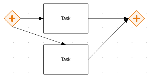
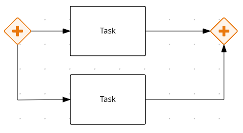
As an example, consider the following scenario. When creating a basic BPMN split structure in the actual state of the editor, it results in something like shown in the below's west image, although what's expected is shown in the east image:
Goal
Provide a faster (less clicks) and intuitive way to create and manage BPMN layouts, by making easier and more friendly usage of lines and orthogonality between segments.
For example, considering the gateway example above, the user needs several clicks and the creation and positioning of bendpoints just to create the structure. This approach is too slow and not friendly enough. So what is expected is doing it by just clicking twice on the gateways's contextual menu - create task icon.
Acceptance Criteria
- Line becomes a composition of 2 types of segments:
- "Orthogonal" (relative to the X/Y axis)
- Horizontal (west <-> east) == –
- Vertical (north <-> south) ==> |
- Connected to a fixed or auto magnet , or the combination of both
- Regular ==> / , \ or conneted to center magnet
- [Note] Notice even if 2 segments are defining a 90º degree angle between them, it does not mean those will behave as orthogonal segments. Only H/V segments, relative to the coordinate system (X/Y axis) are behaving as orthogonal, otherwise, it's being considered a regular one
- "Orthogonal" (relative to the X/Y axis)
- Behavior of the segments
- Depending on the direction of the segment, it will behave orthogonal or regular, so behavior changes dynamically given the endings location and so the segment direction
- Orthogonal segments will stay in the same direction while moving the endings when connected to a fixed magnet
- Orthogonal segments may change direction while moving the endings when connected to an auto magnet
- Regular segments may change their direction while moving any of both endings
- In case multiple selection of nodes, all lines and their segments will behave independently, as if both were handled separately
- See example screenshots below
- Drag capabilities for orthogonal segments
- Orthogonal segments can be moved top/down (when H segment), or left/right (when V segment), by dragging the segment handle icon.
- Drag the segment to a new position makes the segment a pinned segment (orange handle)
- If the distance between the two points of the orthogonal segment (the segment is too short) is less than 20 pixels the handle icon won't be shown. Otherwise, the handle icon will overlap the bendpoints of that segment and the user won't be able to interact with them.
- Unpinning an orthogonal segment that was moved to a different position by the user will cause the recalculation of the path depending on the position of the nodes
- Orthogonal segments can be moved top/down (when H segment), or left/right (when V segment), by dragging the segment handle icon.
- Pinning capabilities for orthogonal segments
- There are two types of orthogonal segments to be considered when moving nodes:
- Inferred (blue handle): those created/destroyed automatiacally based on the position of the nodes
- User Defined/pinned (orange handle): those pinned/moved by the user that should keep their position
- if the pinned segment is vertical, it might grow verticaly, however, it must to keep the X coordinate fixed
- if the pinned segment is horizontal, it might grow horizontaly, however, it must keep the Y coordinate fixed
- For pinning/unpinning an orthogonal segment click on the handle icon
- Points of pinned segments are marshalled to the XML, this way when the diagram is reopened they will remain pinned
- There are two types of orthogonal segments to be considered when moving nodes:
- Bendpoints
- Bendpoints will be available for all segments, as it currently works in the polylines
- Users will be able to create new bendpoints, on any segment
- Users will be able to delete new bendpoints, on any segment
- Users will be able to move bendpoints around
- Implications with segments:
- Once moving a bendpoint to a different location, the segment will behave orthogonal or regular given its final direction
- While moving a bendpoint and the angle between the two regular segments reaches 90°, an "L" angle icon will appear next to the bendpoint then if the bendpoint is released the segments will be converted to orthogonal.
- And vice versa
- Magnet selection strategy
- Depends on the location & bounding boxes of both source / target shapes and the type of the connection set (Automatic / Fixed)
-
- Type of connetion can be changed by clicking on the source/target control-point of the line
-
- "A" inside the control-point indicates the connection is set to auto-magnet. The magnet will be be selected automaically based on the position of the source and target nodes.
- "F" inside the control-point indicates the connetion is set to fixed. The magnet won't change if any of the nodes move.
-
- Type of connetion can be changed by clicking on the source/target control-point of the line
- New nodes creation
- New nodes are always created orthogonally
- The connetion between nodes is set to "A" auto-magnet by default for the source and target nodes
- Scope
- This new feature will available in the BPMN editor for both Sequence Flow and Associations for the Kogito stream, available for all channels.
- DMN and BC editors are not in scope
Example usecases
On gateways:
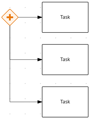
Orthogonal segments:
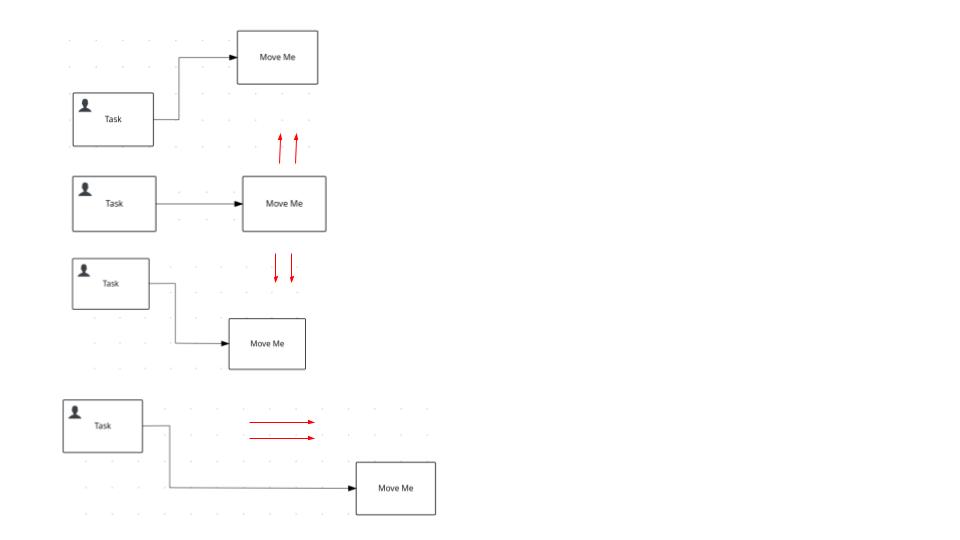
Regular segments:
Known issues and Improvements
- Change the connetion to fixed, pin the vertical orthogonal segment, move the target node vertically to below the source node then move the target shape around until some points reach the same coordinates. There will be more than one point at the same coordinates. A possible solution is to merge the points in the same coordinates or somehow prevent the points from reaching same coordinates.
- Orthogonality is broken in some situations: source/target nodes overlap
- With the magnets auto by default, pin a vertical segment and move the taget shape vertically(only Y) to be above or below the source shape, then unpin the segment. It will cause the line to be rebuilt but the old handle and control points are not being destroyed.
- Inprove the magnet selection to consider free magnets in order to reduce the overlap of lines.
Nice to Have
Some features that have been discussed as well, but not yet in scope. If not feasible to include some of those during the given timeframe, can be reported in a new ticket for a further work.
- A trash icon available to drop a concrete bendpoint (also can be dropped by dbl clicking on it, as actually works)
- A trash icon available to drop the whole line
- is related to
-
KOGITO-7644 Lienzo - Native Support for orthogonal segments in lines
-
- Closed
-
-
KOGITO-4413 Implement - designs for orthogonal lines between diagram nodes
-
- Closed
-